Understanding Elements
Elements are the fundamental components used to build complex mechanical linkage systems.
Connectors

Connector
A connector is the point where one link connects to another, or simply a marked location in your mechanism. Connectors are drawn as small circles. A connector doesn't need to be attached to anything — on its own, it just marks a point in space.
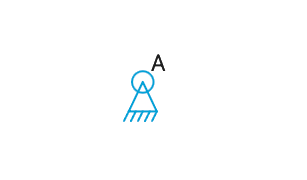
Anchor
An anchor is a connector affixed to the ground of the mechanism, a hidden, fixed link that everything else is ultimately built on, like the frame of a truck or the floor of a factory. Anchors don't move during simulation; anything connected to one is free to rotate around that fixed point.
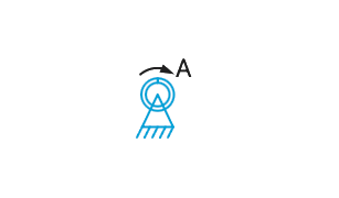
Motor
A motor is a rotating anchor. Anything attached or fastened to it rotates along with it during simulation. Set its rotation speed in Revolutions Per Minute (RPM) and choose whether it turns clockwise or counter-clockwise, along with other motor-specific properties like an oscillation limit for back-and-forth movement instead of continuous rotation.
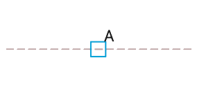
Slider
A slider is a connector that follows a path instead of moving freely, tracing a straight line, an arc, or a spline as the mechanism moves. Sliders are drawn as squares rather than circles, rotated to align with the direction of their path at each moment.
Tip: Connectors, along with dimension lines, labels, and other on-screen indicators, do not change size when zooming. The circle marking a connector's location has no innate size within the mechanism itself; it's just showing you where the connector is and what its status is, at a size that stays readable no matter how far you zoom in or out.
Links
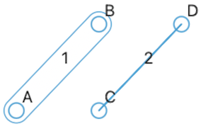
Link
A link represents a rigid piece of material connecting two or more connectors together, like a bone, a lever, or a bracket. A link's shape and length stay fixed unless you resize it while editing — during simulation, links move and rotate but never stretch.
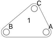
Tip: A link isn't limited to two connectors. Add more connectors to a link to build shapes like triangles or brackets, useful when you need a single rigid part with more than two attachment points.
Linear Actuator
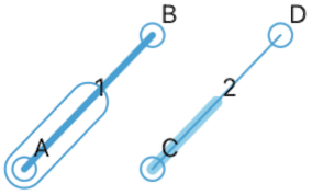
A linear actuator is a special kind of link that changes length during simulation, like a hydraulic piston. Set its cycle speed in Cycles Per Minute (CPM). It can also be set to have Always Manual Operation, letting you control its extension by hand during any simulation instead of moving automatically.
Gears
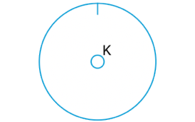
A gear transfers rotational movement to another gear, either by meshing directly or through a chain connection. Set the ratio between two gears to control their relative speed and size.
Tip: A gear is really a link that's drawn and behaves like a gear. Usually you'll only see its center connector, but you can add more connectors to it just like any link. Added connectors rotate with the gear, as if welded to it, a way to attach a lever directly to a gear.
Splines

A spline is a shape made of connected lines and curves, useful for drawing something more complex than a link's straight-edged outline. A spline can be open, with a distinct start and end, or closed, forming a continuous loop. On its own, a spline is purely visual, letting you show the true outline of a part beyond what its connectors define. A spline can also be used as a path for a slider, in which case it works much like a cam.
Points

Point
A point marks a single location in your drawing, similar to a connector, but purely for reference or decoration; it doesn't participate in the mechanism's simulation.
Tip: Connectors and links always show a label, either an automatic identifier like a letter or number, or a name you've typed in. Points don't show an automatic identifier, but naming a point is a way to add annotation text to your mechanism exactly where you want it.
Circle
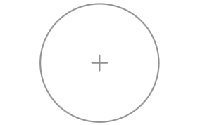
A circle is a point with a radius set, drawing a circle of that size around it, useful for marking a hole, a boundary, or any round feature your mechanism doesn't otherwise define.
Lines
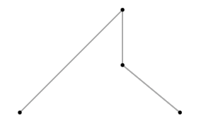
Polyline
A polyline is a drawing element made of two or more points connected together, similar to a link but purely visual; it doesn't participate in the mechanism's simulation. Each segment is drawn individually, without closing the shape.
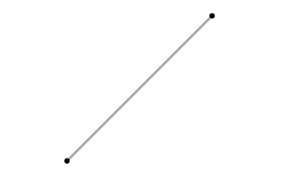
Line
A line is a polyline with only two points, drawn as a single straight segment between them.
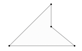
Polygon
With three or more points, a polyline can instead be drawn as a polygon, closing the shape and filling it in, connecting the last point back to the first.
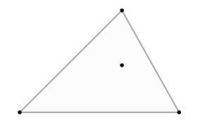
Hull
A polyline can also be drawn as a hull, tracing the outer boundary around all of its points and skipping any that would create a concave dent in the shape. This is how all mechanism links are drawn.
Measurements
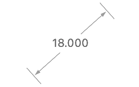
Linear Measurement
A measurement line shows the distance between its two endpoints.
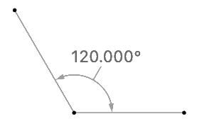
Angle Measurement
An angle measurement shows the angle formed at its center point, measured between lines drawn to its two other points.
Tip: Fastening a measurement's points to other elements lets it track a distance or angle that changes as your mechanism moves, rather than staying fixed in place. This works the same way for both measurement lines and angle measurements.
Guidelines
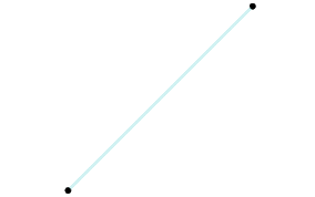
A guideline is a line used to help position other elements while editing. Connectors and points snap to a guideline as they're dragged near it, along its full length, not just between its endpoints, and to the intersection of two guidelines. Guidelines are visible while editing but don't appear in printed output.